Just gimme the files
Grab the stuff from here if you know what you're doing:
Build files
Schematics
BOMs
Enclosure
Drill map coming soon!
Overview
The HOG by Shmøergh is a fully-analog monophonic synthesizer. Its purposeful limitations make it a great instrument for live performances. The HOG uses switches over knobs to change sounds quickly and without having to use presets which converts the signal to digital. To learn more about its features checkout the HOG user guide.
The HOG is an open source DIY synth. This page contains information that allows anyone to build one.
Disclaimer
All electronic projects and designs presented on this web site, or associated web sites should be considered dangerous if not lethal if not used safely. When working on projects based on the designs on this site, use extreme care to ensure that you do not come into contact with mains AC voltages or high voltage DC. If you are not confident about working with mains voltages, or high voltages, or you are not legally allowed to work with mains voltages, or high voltages, you are advised not to attempt work on them. The author, host, and all people associated with these web pages disclaim any liability for damages should anyone be killed or injured while working on these projects, or projects based on these designs, or any other project or design presented on these web pages and any associated web pages. The author, host, and all people associated with these web pages also disclaim any liability for projects, or projects based on these designs, or any other project or design presented on these web pages and any associated web pages when used in such a way as to infringe relevant government regulations and by-laws.
All circuits, schematics, printed circuit board, panel design and associated data published on this site can be used for private use only.
We are not responsible for any errors in the PCB design or the parts list. All responsibility for ordering PCBs, components, and assembly services rests solely with you.
License
Shmoergh Hog © 2024
Hardware is licensed under CC BY-NC 4.0
Software is licensed under MIT.
This synth is open source but according to the CC BY-NC license you cannot build HOGs for commercial purposes only for personal use. We're super interested in your builds so please share it with us down in the comments or on Instagram.
Prerequisites
Knowledge
Tools
During the build process you’ll need the following:
- Your computer to keep track of the schematics and PCBs. You’ll need to install KiCAD 8 or higher, it’s free
- Soldering station and smoke extractor
- Oscilloscope
- Multimeter
- Tuner with line input, or an audio interface to tune the oscillators
- Precision screwdrivers, pliers
- 14 pcs of M3x20 screws to secure boards together
- A controller with CV/Gate output (e.g. Arturia Keystep) [recommended], or a MIDI keyboard
Time
If you have all the PCBs and components it takes about a week to build a complete HOG, depending on your experience level in synth DIY and electronics.
Build variations
While you can build a complete HOG from the above files and this guide, you can use the schematics or even the boards separately.
Custom analog synth / Eurorack synth module
The core is actually a fully-featured standalone analog synthesizer module with two oscillators, sub oscillator, two LFOs, a VCA a mixer and an ADSR. It has all the inputs and outputs avaliable on the PCB, so if you understand electronics and study the Core circuits you can design your own control panel for it. You can create a drone synth with complex cross modulations, use knobs for each function for a sound-design-centric instrument — the possibilities are endless. It’s also Eurorack compatible both in terms of size (100mm height) and power (works with +/- 12V and uses Eurorack power connector).
Reusing schematics
The Core board is separated to functional sheets: the VCOs, ADSR, VCA etc. are all on their own schematic sheet. They’re fully working and tested so nothing stops you to reuse these circuits in your own designs.
Filter
The HOG has a super drippy Steiner-Parker low-pass filter with some minor modifications. Just like the Core board it’s also a fully standalone Eurorack compatible module, you can design your own panel for it and stick it in your Eurorack case.
MIDI2CV converter
The MIDI2CV converter has a MIDI input and 2 pitch and 2 gate outputs. Like the Core and Filter boards, it’s Eurorack compatible and uses super basic components. Similarly to the rest, you can reuse this to build a separate 2 channel MIDI to CV converter. It uses an actual Raspberry Pi Pico and you can find the code for the default implementation in the repo.
Board setup
The HOG is built up of 5 PCBs or boards.
- PSU board — power supply board that converts 12V DC to +/-12V
- Core board — contains all the modules that make and shape the sound, except for the filter
- UI board — the control panel of the synth with all the switches and knobs. All the other boards connect to this
- Filter board — a Steiner-Parker voltage controlled low-pass filter
- MIDI2CV — a board converts MIDI signal to control voltage

These boards connect to each other through pin headers and sockets so there’s literally no cabling involved in the build. The Core and Filter boards have both SMD and through hole components, the rest is through hole only.
Build material & files
All the files for the HOG build are available at the Shmøergh HOG Github repo. Click on Code / Download ZIP to get them. Here’s a breakdown of each folder:
board— contains folders for each board with KiCAD schematics, PCB design and production filesboard/[boardname]/production— this folder contains the gerber files for PCB and the BOMs
simulations— CircuitJS simulations we’ve used during the design process
BOMs
As written above you’ll find BOMs for each board in its respective folder under the production directory. Each vendor’s BOM is separated into further folders. For example the Core board’s BOMs can be found in board/core/stable/production Here you’ll find a jlcpcb folder which contains the gerber files, the BOM and positioning files for SMD components to order from JLCPCB. You’ll also find a mouser folder which contains the through hole components that can be ordered from Mouser using the corresponding CSV file.
The switches
There’s been a lot of questions about where to get those cool switches, so here they are. There are two types of switches used, both manufactured by Daier China.

| Switch type | Part number |
| DPDT | TS22-E01 |
| DP3T | TS23-E02 |
Ordering PCBs
Each PCB board can and should be ordered separately. The production/jlcpcb folder contains a .zip file for each board that you can use to order PCBs from JLCPCB. If you want to order from another PCB manufacturer, you’ll need to generate the gerber files for yourself.
The ordering process from JLCPCB is quite straightforward, you just upload the zip file and leave all defaults.
SMD assembly
The Core and the Filter boards contain SMD components which is super-hard to build by hand. 99.99% of these components are available at JLCPCB and the production/jlcpcb folder for each board contains both the BOM (bom.csv) and the positioning files (positions.csv) to order assembly from JLCPCB.
Check out this video (from about 12:00) to learn how to order PCB assembly from JLCPCB.
Through hole components
All 5 boards have through hole components which you have to order and hand build. Almost all the parts are available at Mouser (except for the switches on the UI board) and the production/mouser folder contains CSV files for each board that you can use to order all components from Mouser. Here’s how:
- Go to https://www.mouser.com and log in with your account
- Open BOMs from the account menu
- Click on Create New BOM
- Upload the
./mouser/[board]-mouser-bom.csvfile from this directory - Make sure you map the
Quantity 1andMouser Product Numbercolumns correctly - Create the BOM on Mouser
You can order all necessary parts at once. If a part is not available you need to find replacement components, or if you want another vendor (like Digikey) then you'll need to find all parts yourself.
For through hole components in general we recommend to start soldering passives – like resistors and capacitors – first. Then move on with semiconductors and integrated circuits. We also recommend using IC slots instead of soldering the ICs directly on the board. Doublecheck for power shorts (+12V → GND, +12V → -12V, -12V → GND) before inserting ICs.
Checklist
PSU board
- [ ] Order PCB
- [ ] Order through hole components
- [ ] Solder through hole components
Core board
- [ ] Order PCB
- [ ] Order SMD assembly
- [ ] Order through hole components
- [ ] Solder through hole components
UI board
- [ ] Order PCB
- [ ] Order through hole components
- [ ] Solder through hole components
Filter board
- [ ] Order PCB
- [ ] Order SMD assembly
- [ ] Order through hole components
- [ ] Solder through hole components
MIDI2CV board (optional)
- [ ] Order PCB
- [ ] Order through hole components
- [ ] Solder through hole components
Board assembly and tuning
- [ ] Connect PSU board to UI board
- [ ] Connect Core board to UI board
- [ ] Connect Filter board to UI board
- [ ] Connect MIDI2CV to UI board (optional)
- [ ] Tuning process (see later)
Board breakdown
In this guide we’re not going to show how and when to solder each and every component, only the ones which need special attention. To build these boards you’ll need to read their schematics and PCBs in KiCAD and find where to solder each component. We assume you know these basics and if not, you’ll learn it before getting into building a HOG.
PSU board
Files: /boards/psu
Components: Through hole only
This is the simplest board with only three component: a fully built Mean Well voltage converter (NSD10-12D12) that creates +/-12V from a 12V DC input and two pin sockets.
Notes
- The pin sockets on the board should be soldered upwards, on the front layer.
Testing
- Connect a 12V power source to the 12V and GND INPUT pins and measure the output voltages with a multimeter. The output voltages should be +/-12V.
Core board
Files: /boards/core/stable/
Components: SMD and through hole
Here’s the block diagram of the HOG:

The core board contains all the fundamental modules of an analog synthesizer, namely:
- 2x VCO: generates a 1V/octave raw sawtooth according to the input control voltage (CV)
- 2x Waveshapers: creates AC coupled triangle, sawtooth and pulse width adjustable square waves from the raw sawtooth signal
- Noise and sub source: generates white noise and a square wave 1 and 2 octaves lower than the actual pitch of VCO1. The ratio of -1 and -2 octaves is adjustable.
- Mixer: mixes all the sound sources into a single output
- VCA: takes the output of the mixer and sets its volume according to a control voltage that’s coming from the envelope generator (ADSR)
- ADSR: the envelope generator that outputs a control voltage to set the output volume
- 2x LFO: LFOs to modulate pitch, filter cutoff and other parameters
- Output: normalizes the final audio output and includes a dual-mono headphone amplifier
SMD
As mentioned above the Core board has quiet a lot of SMD components. You can order them following the SMD assembly process.
Notes
- The Core board has 4 SMD components that are not available at JLCPCB so you’ll need to solder them manually. All of these components are included in the Mouser BOM so you can order it from them. They are:
- Q203 and Q206 — MMBFJ111
- TH201 and TH202 — PTS120601B100RP100
- The pin sockets on the board should be soldered upwards, on the top layer.
Through hole components
The BOM for the through hole components is available in the /boards/core/stable/production/mouser folder and can be ordered from Mouser using the ordering process.
Filter board
Files: /boards/steiner-parker-vcf/
Components: SMD and through hole
Follow the same process for SMD assembly and through hole components as for the Core board.
Notes
- Don’t solder the Eurorack power connector! That’s only needed if the filter board is used as a separate Eurorack module.
- Connect the bottom 2 pin of the
JP_INT_EXT1jumper. This allows several cutoff control voltages to connect to the filter. - The 2x8 pin socket on the board should be soldered upwards, on the front layer

UI board
Files: /boards/ui/
Components: Through hole only
Follow the same process for through hole components as for the Core board.
Notes
- All the pin headers on the UI board should be soldered on the bottom layer of the board because all the other boards connect to the UI board from the bottom.
MIDI2CV board
Files: /boards/midi2cv/
Components: Through hole only
Follow the same process for through hole components as for the Core board.
Notes
- The MIDI2CV converter uses a Raspberry Pi Pico board, which you should solder directly to the board (without headers) in order to fit the height with the connection to the UI board.
- The pin sockets on the board should be soldered upwards, on the front layer.
Uploading the MIDI2CV firmware
- Download the firmware
- Push the Boot button on the Pico and connect it to your computer. The Pico should appear as a drive on your computer
- Drag and drop the firmware file to the Pico. The Pico should automatically eject from your computer
Board assembly
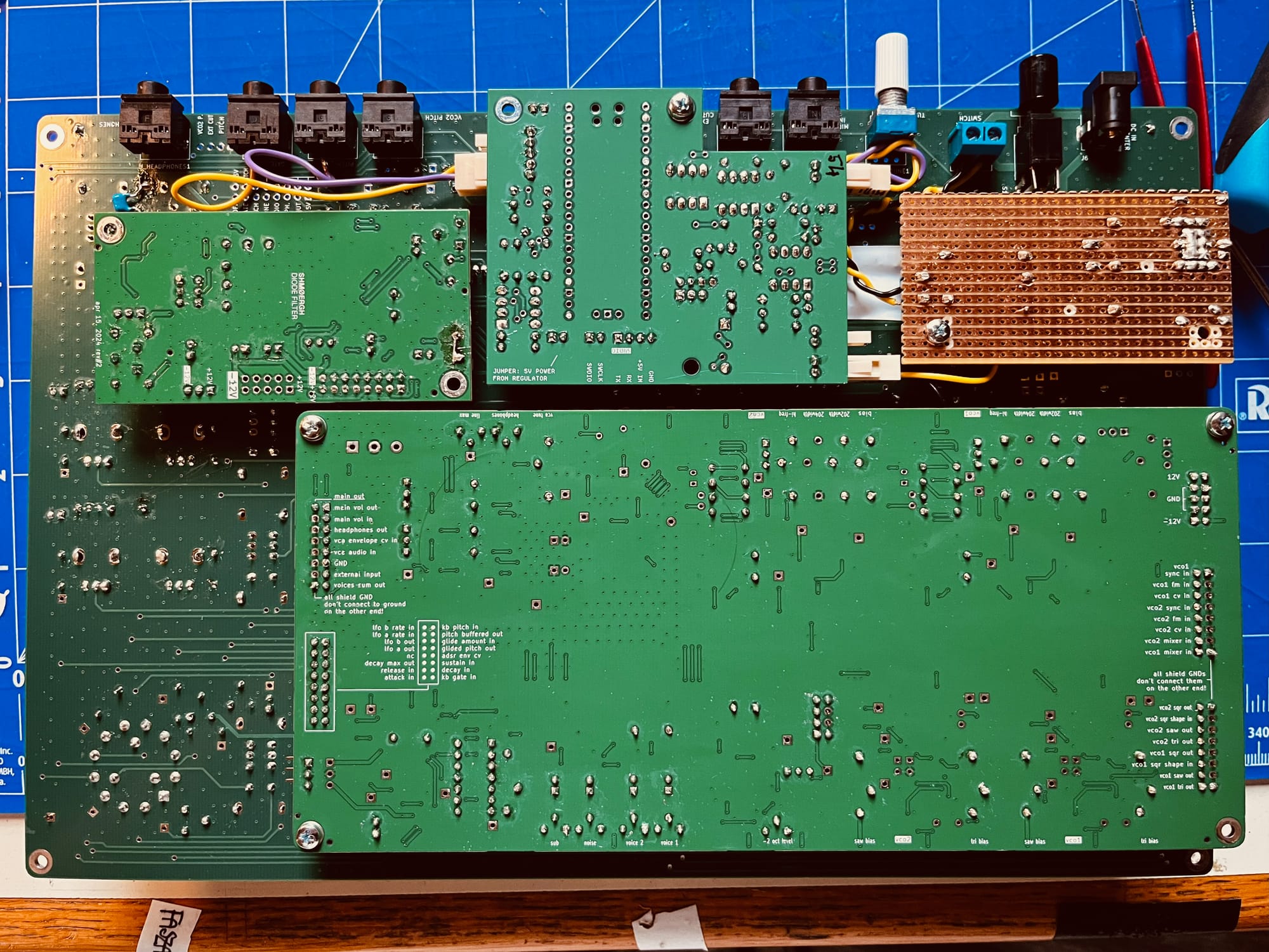
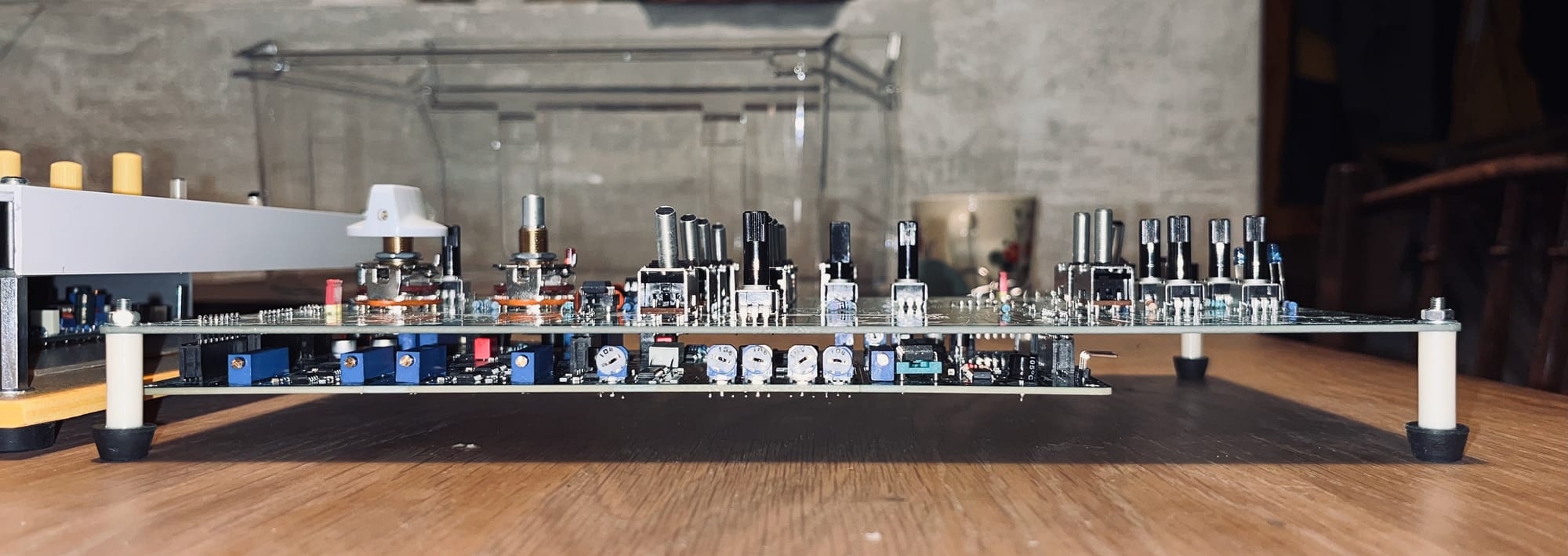
The PSU, Core, Filter and MIDI2CV boards should be connected to the UI board from the bottom via their respective pin sockets. Use M3 screws to secure the boards to each other.
1 — Insert the PSU board into the UI board

2 — Insert the Core board to the UI board

3 — Insert the Filter board to the UI board

4 — (Optional) Insert the MIDI2CV board to the UI board

Here’s is a picture of an earlier HOG prototype from the bottom and front. Note that this is not the latest version, it still has some hacks, cables and the PSU board is home made, but yours should look very similar once all boards are connected up.
Tuning
Preparation
To finish tuning the HOG you’ll need to:
- Connect an oscilloscope to the main output
- Connect a CV/Gate compatible controller (e.g. an Arturia Keystep) to Pitch and Gate or a MIDI controller to the MIDI input (in case
- Connect two jumpers: JP_VCO1_IN1 and the middle and right pin of JP_PHO-LINE1

Troubleshooting
Ideally you should hear some sound on the output. If not then that can be for a couple of reasons:
- Make sure you connected your keyboard to the appropriate inputs (Pitch, Gate)
- Make sure
RV_LINE_OUT_LVL201andRV_HEADPHONE_LIM201on the Core board are all the way up. They set the line and headphone output volumes. - Make sure
RV_201,RV_202,RV_204andRV_205on the Core board are all the way up. They set the individual sound source (VCOs, noise and sub) levels. - Play with
RV_SUSTAIN_MAX1(UI board) andADSR_MAXtrimmers. Both should be relatively up to make sure ADSR starts triggering.
Wave shapes

Turn the VCO1 waveform selector on the UI board to sawtooth (position #2). Make sure you turn off VCO2 (Fat) on the UI board. Switch on HOLD on the UI board and hold a note on your controller or keyboard.

On the Core board:
- Tune
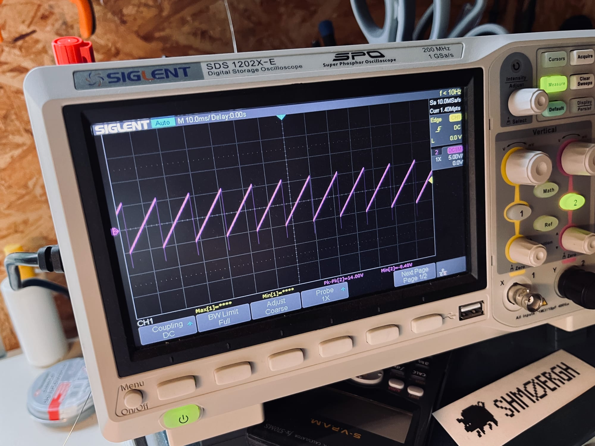
VCO1 SAW BIASuntil the output shows a sawtooth that oscillates around 0V

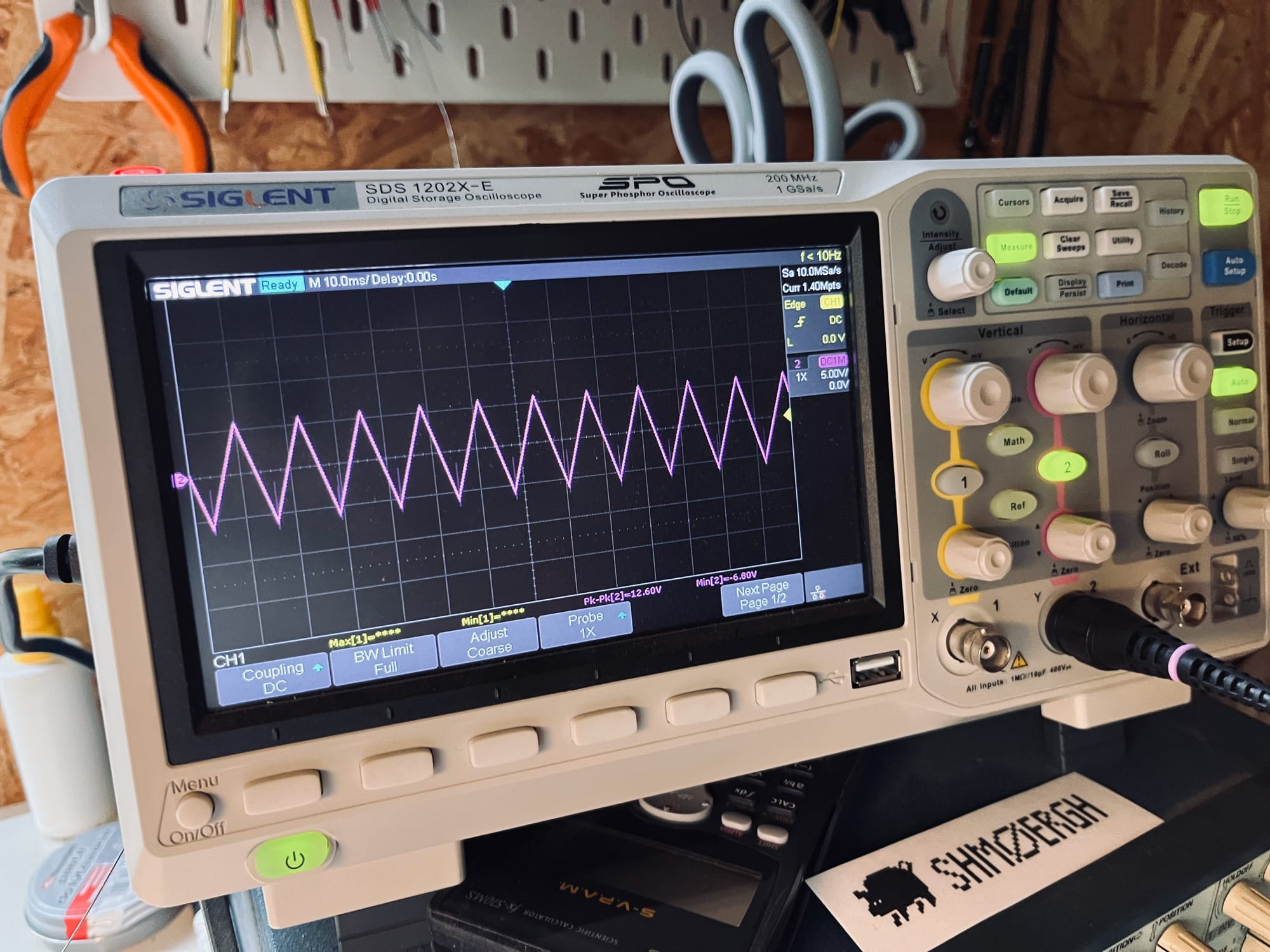
- Turn the VCO1 waveform selector to triangle waveform. Tune
VCO TRIANGLE BIASuntil you see a perfect triangle on the oscilloscope.

- Turn the waveform selector to narrow pulse (position #4) and use the
RV_NARROW_WIDTH1trimmer to set the pulse width for fixed narrow square wave. - Turn the waveform selector to PWM (position #5) and use the
RV_PWM_LEVEL1to set the level of pulse width modulation. Note that the frequency of the PWM comes from LFO2
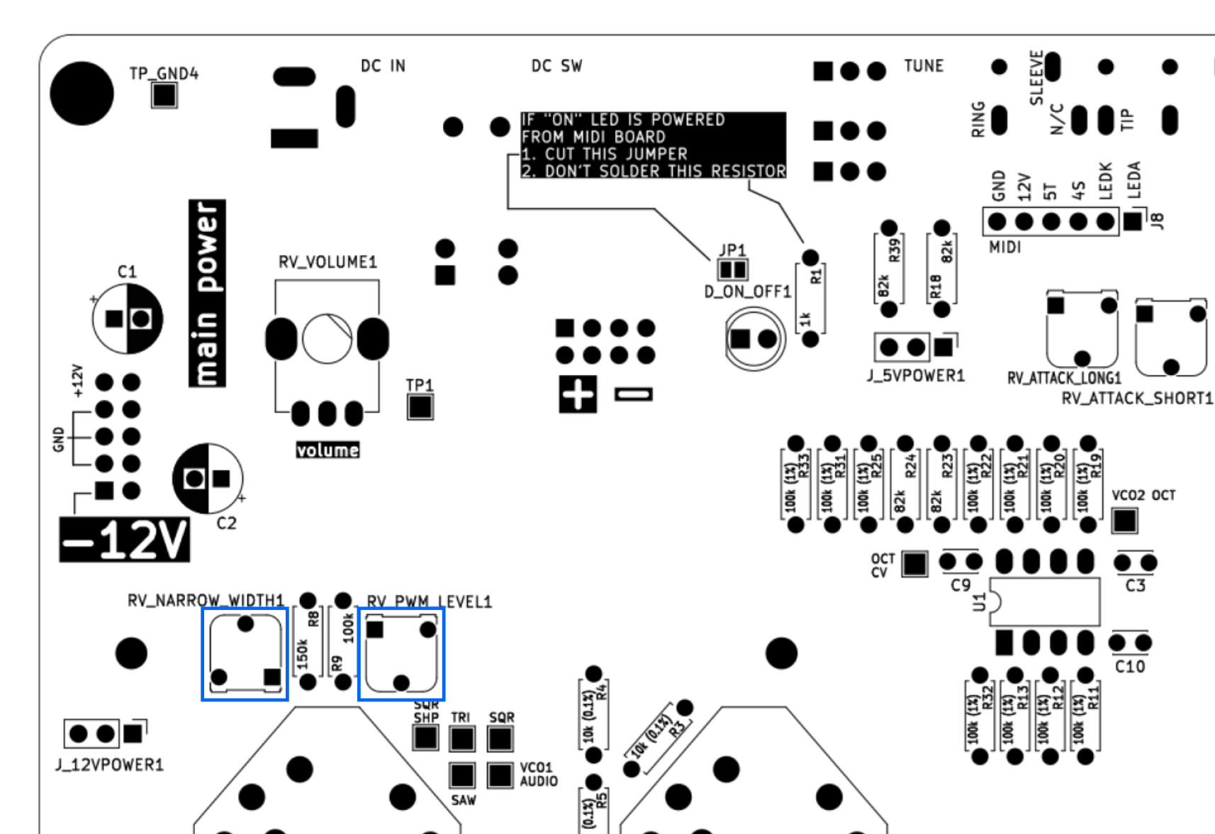
Then set the same for VCO2:
- Disconnect JP_VCO1_IN1 — this will disconnect VCO1 from the output so you can monitor and listen VCO2 only
- Repeat steps 1-2 with
VCO2 SAW BIASandVCO2 TRIANGLE BIAStrimmers. Use theSW_VCO2_WAVE1switch to switch between triangle, sawtooth and square waves.
Octaves
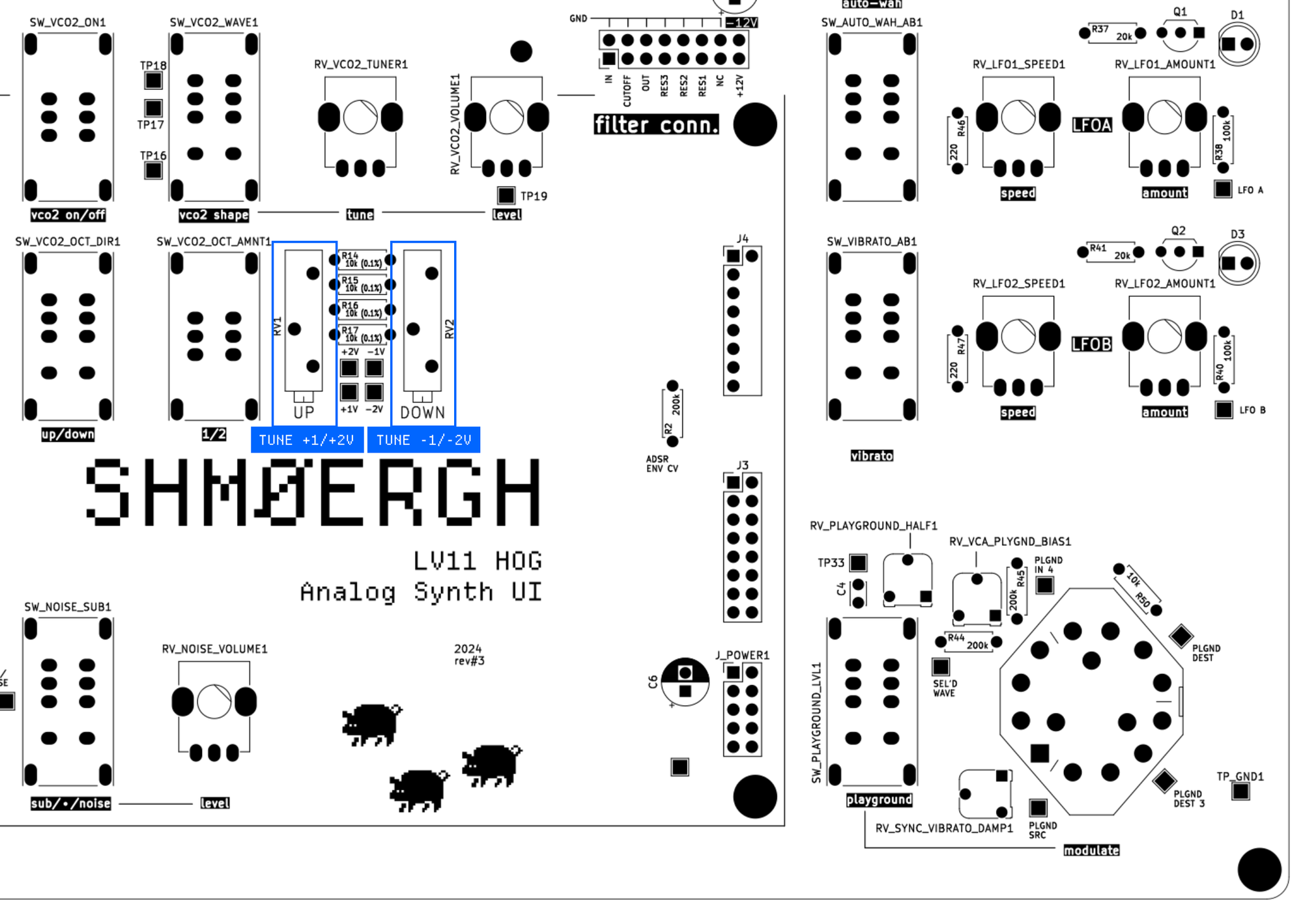
This tuning is critical so that the main octave and the VCO2 octave switches work accurately.
- On the UI board tune the +/-5V voltage source to exactly +/-5V
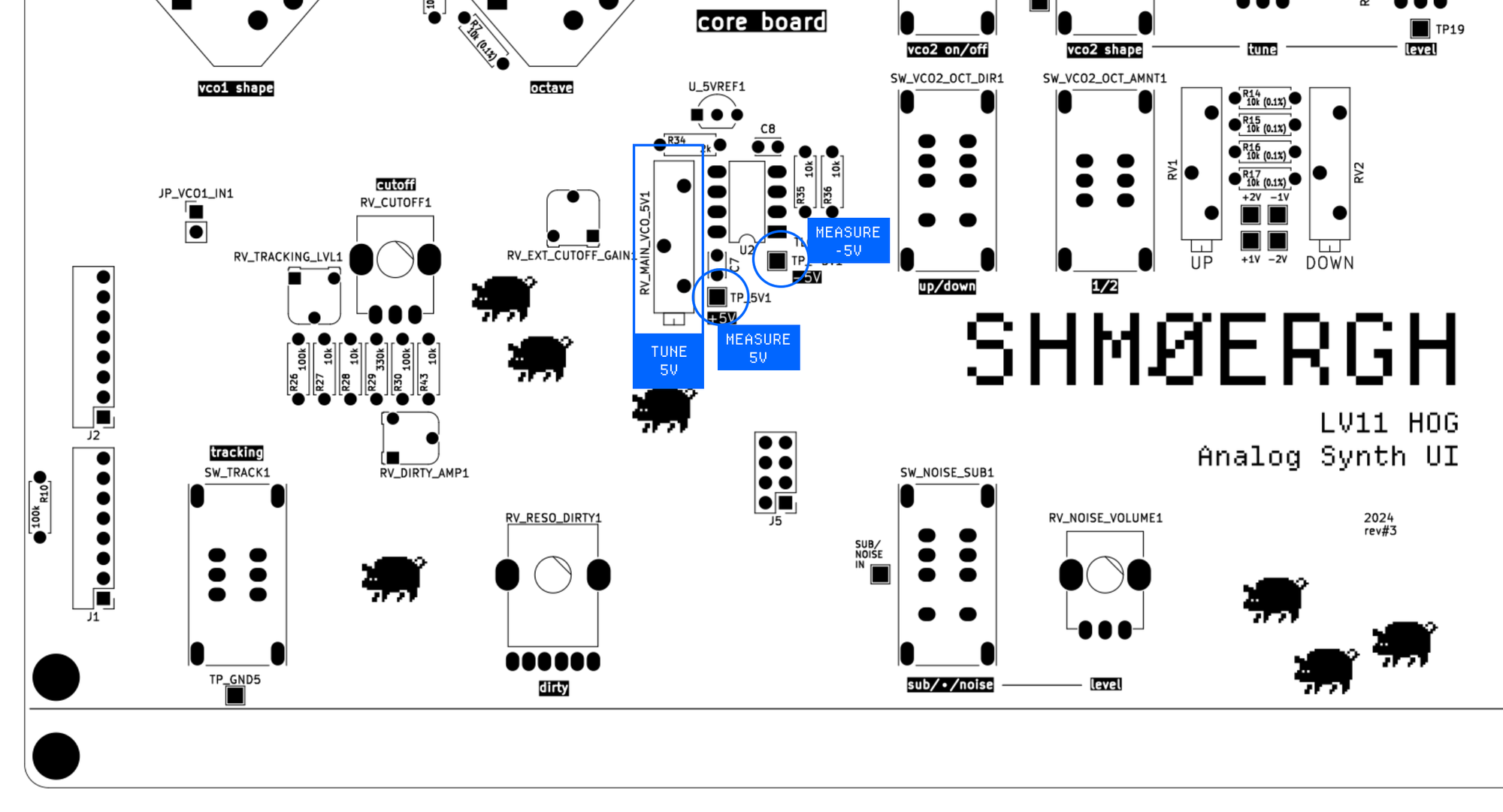
- On the UI board tune the +1/+2 and -1/-2 octaves of VCO2.
ADSR
You need to hit notes on your keyboard and watch the output on the oscilloscope to test the ADSR.
- Connect the oscilloscope to the ADSR output (from the bottom of the Core board)

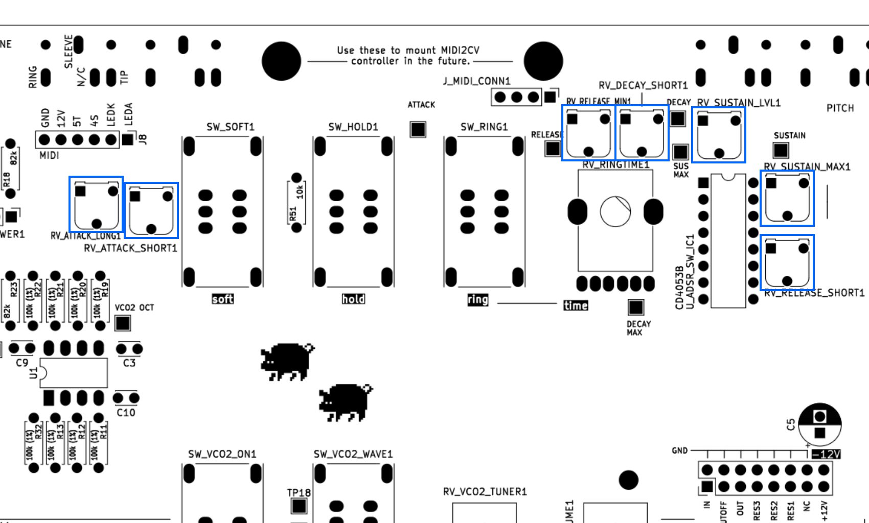
- Play notes on your keyboard and set the max voltage of the ADSR to about 8V with the
ADSR MAXtrimmer. Check the output on the oscilloscope. If you can’t achieve 8V make sure thatRV_SUSTAIN_MAX1trimmer on the UI board is all the way up. - On the UI board use the following trimmers to fine tune the ADSR values according to the following:
RV_ATTACK_LONG1 | Sets the attack value when the Soft switch is on |
RV_ATTACK_SHORT1 | Sets minimum attack value when the Soft switch is off. This allows to eliminate the pop on short attack |
RV_RELEASE_MIN1 | Sets minimum release value |
RV_DECAY_SHORT1 | Sets the decay time to the sustain value when Hold is on |
RV_SUSTAIN_LVL1 | Sets the sustain level of the ADSR. This allows to have a lower sustain value when Hold is on |
RV_SUSTAIN_MAX1 | Sets the maximum sustain value. |
RV_RELEASE_SHORT1 | Sets minimum release when Ring is off. Allows to fine tune the length of the envelope when all ADSR switches are off |
VCO tuning
This is the part when you tune the VCOs to 1V/octave standard tuning. Connect a tuner or an audio interface with a DAW and a tuner plugin to your output. Play the C1 note (that’s around 32Hz). These are the trimmers we’re going to use on the Core board:

We’ll tune VCO1 first, so turn off VCO2 just like you did at the wave shape tuning.
- Turn
VCO1 HI-FREQall the way down so there's no high frequency compensation (VCOs tend to go flat on higher frequencies, this trimmer is to compensate that). To make sure it’s all the way down play a very high pitch note and start turning the trimpot so that the pitch is going down. Once it doesn't go lower then you "turned off" high freq compensation. - Use
VCO1 BIASto set the frequency to C1 (32.703Hz) - Play C4 and use
VCO1 BIASto set the frequency to C4 (261.63Hz) - Play C1 and use
VCO1 WIDTHto tune it to 32.703Hz) - Loop Step 3 and 4 until C1 and C4 are both in tune
- When C1 and C4 are in tune, play higher octave C's and use
VCO1 HI-FREQto adjust tuning for them.
If needed, repeat steps 3 and 4 for other note pairs.
To tune VCO2, remove the JP_VCO1_IN1 jumper and turn on VCO2. Repeat the steps with the VCO2 trimmers.
Sound source volumes
With these trimmers you can set the maximum volume for each sound source: VCO1, VCO2, noise and sub. Additionally you can mix the volume of -1 and -2 octave of the sub oscillator with SUB -2 OCTAVE LEVEL. For line level maximum about 1.6Vpp is recommended on the output.

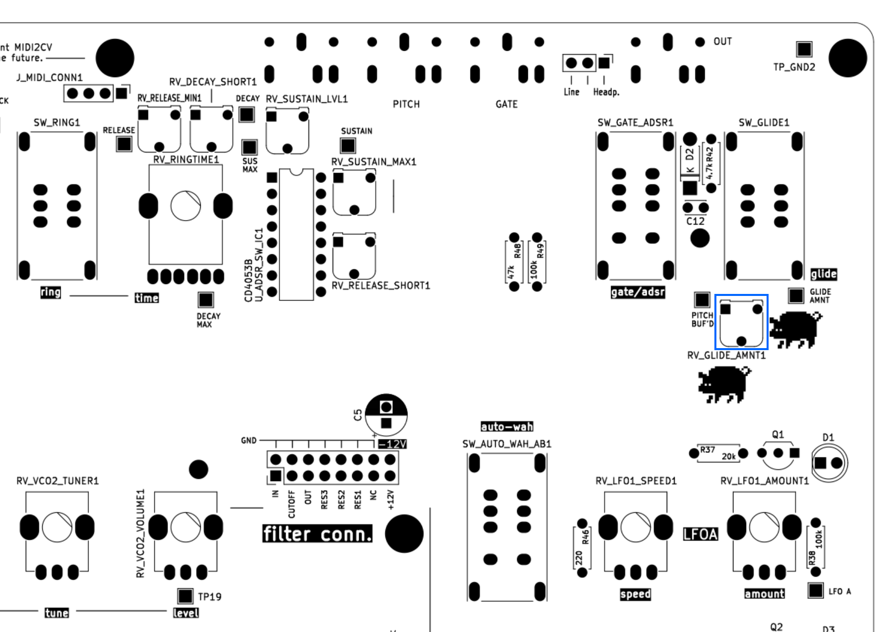
Glide amount
Use this trimmer to set the fixed glide amount when glide is on:
Playground
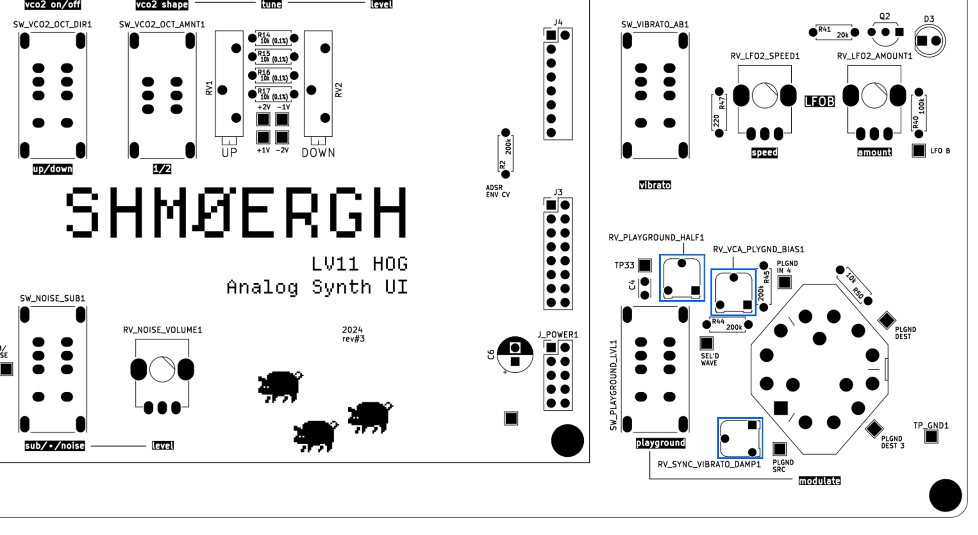
The following parameters of the Playground section can be set:
RV_PLAYGROUND_HALF1 | Sets the amount of modulation when the Playground ON/OFF switch is in the middle. |
RV_VCA_PLAYGND_BIAS1 | Sets the control voltage sent to the VCA when the Playground switch is set to position #4 (ring modulation) |
RV_SYNC_VIBRATO_DAMP1 | Sets how much LFO2 should modulate the detune of VCO2 when Playground is in position #1 (hard sync) |
Filter tuning
Use the CUTOFF_BIAS trimmer to set the minimum cutoff control voltage for the filter, and the MAX RESONANCE trimmer to set how much the filter should resonate when the “Dirty” pot is set all the way up.

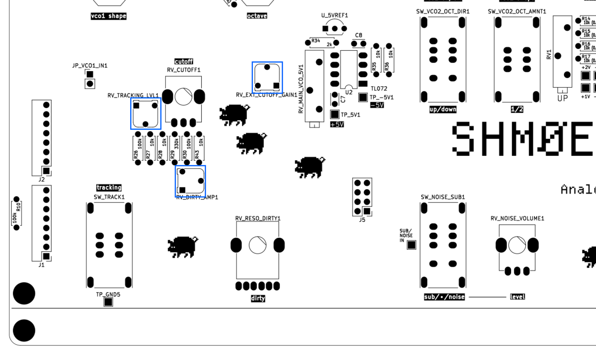
On the UI board you can fine tune a couple of filter related things:
RV_TRACKING_LVL1 | Sets the maximum value of the tracking. When tracking is on then the higher the note the more the filter will open. |
RV_EXT_CUTOFF_GAIN1 | Sets the level of external cutoff from a gain of 0 to 2 |
RV_DIRTY_AMP1 | Sets how much the ADSR should effect the cutoff when resonance is turned up. (The resonance and the envelope modulation happens at once via a dual pot.) |
Output volumes
Use the HEADPHONES LEVEL and LINE LEVEL respectively to set their maximum values. Note that LINE LEVEL sets the maximum input level for HEADPHONES LEVEL too.

Enclosure
We've put the HOG in a custom sheet metal enclosure. We'd like to keep the designs for this enclosure private, but here we're sharing a PDF drill guide for the top and back panels which you can use to design your own enclosure.
Top panel
The size of the top panel is 290x190mm, and it's designed using a 10x10mm grid, ie. all the knob, LED, toggle and rotary switch holes fall on the intersection of these grid lines. The size of the hole is indicated on top, but here's a breakdown of each drill type
| Pots | 10mm |
| LED | 3.5mm (if you use 3mm LEDs) |
| Toggle switches | 7x15mm |
| Rotary switches | 10mm |

Back panel
The back panel doesn't use a fixed grid but all hole position and size is marked on the layout guide.

Shielding notes
The VCA and the filter are two extremely sensitive circuits which are susceptible to external noise. Without proper shielding both these circuits will generate noise e.g. when you touch or even get close to them with your finger—we all practically act like huge noise antennas.
To overcome this problem we highly recommend to put the whole synth in a metal enclosure which is connected to common (GND — there are plenty of GND connections on the UI board), or at a minimum shield the Filter and the VCA part of the Core board from the top and bottom.
Questions, bugs
If you have questions, we are happy to answer them in the comments section below. Should you find a bug, please report a Github issue about it. Thx ✌️